

FRP Tank and Vessel In Water Treatment
- Suitable for commercial or industrial water treatment
- Composite fiberglass structure with excellent corrosion resistance
- High strength, light weight, easy to transport and install
- Rotomolded inner lining, seamless structure with no leakage
- High-strength RTM/SMC base
Kysearo specializes in the production of high-quality fiberglass reinforced plastic (FRP) tanks, we offer a wide range of diameters, from 07 inches (180 mm) to 72 inches (1800 mm). These frp tanks are specifically designed for multimedia filters and water softeners, perfectly aligning with the operational requirements of such equipment. Leveraging the superior corrosion resistance, strength, and durability of FRP material, these tanks provide reliable container support for medium filtration and water softening processes, ensuring the efficient and stable operation of the system.
- PE(Polyethylene) seamless one-piece tank liner;
- 4″precision injected model with threaded opening for07″~36″dia. tanks
- 6″ Aluminum alloy flange opening for36″~72″, dia. tanks;
- Continuous strands of fiber-glass with high strength Epoxy resin;
- Completely rust and corrosion free; FRP reinforced tripod base
Materials of construction
Polyethylene (PE) inner shell
Continuous Fiberglass with Epoxy resin roving at outer shell
Max. working pressure:1.0MPa(150PSI) Working temperature:1-49℃
Max.Vacuum:127mmHg(5″mmHg)

Your Premier FRP Tank and Vessel Manufacturer
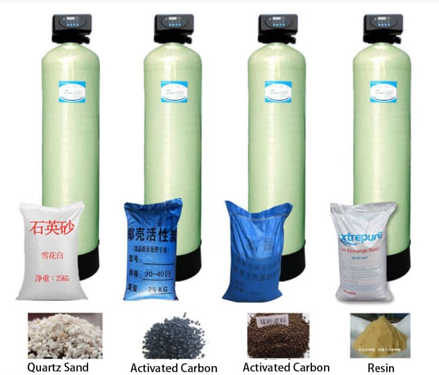
KYsearo FRP vessel container is a water therapy device constructed from glass-fiber-reinforced plastic (FRP) as the tank product, which can be loaded with filter media such as quartz sand, turned on carbon, and manganese sand. It is utilized to remove pollutants such as put on hold solids, colloids, raw material, and odors from water. It is widely applied in fields such as drinking water purification, wastewater treatment, and commercial water pretreatment.
- Operating temperature: 5 ° C-60 ° C( adjustable approximately 80 ° C for unique materials).
- Inlet/outlet size: DN50-DN300 (depending on design).
- Link type: Flange link (PN1.0/ PN1.6).
- Storage tank wall thickness: 8-15mm (computed based upon size and stress).
- Securing Type: Nitrile rubber seal ring (food-grade silicone offered as a choice).
- Control Approach: Hands-on valve control/ Automatic multi-port shutoff control (optional).
Customization
- Special Size: 300 mm– 3000 mm.
- Pressure rating: As much as 1.6 MPa.
- Unique user interfaces: Personalized side inlet/outlet, multi-port design.
- Lining material: Criterion epoxy material (ideal for general water high quality), vinyl ester material (suitable for acidic/alkaline water high quality).
รับโซลูชั่นทันที
The Working Principle of FRP Tanks
1. Purification principle
- Raw water enters the filter storage tank through the inlet pipe and is uniformly distributed throughout the filter media layer through the distributor.
- Water moves downward with the filter media layer , with put on hold solids, colloids, and other impurities being maintained and adsorbed by the filter media. Clean water is collected by the collection agency and released with the outlet pipe.”.
- When the filter media comes to be saturated with adsorbed contaminations, backwashing is done. Backwash water enters from the bottom, causing the filter media layer to broaden and loosen up, and pollutants are released with the drainpipe pipeline together with the backwash water, recovering the filter media’s filtration capacity.
2. Structural principle
- Storage tank body: FRP wound building , consisting of an inner lining layer (corrosion-resistant), architectural layer (load-bearing), and external protective layer (UV-resistant), with the ability of enduring water stress effects and water top quality corrosion.
- Water circulation system: The leading makes use of a bell-mouth or perforated plate distributor to ensure uniform water circulation distribution and stop local filter media overload.
- Water collection system: The lower utilizes a dome-shaped perforated plate or branch pipe-type water collector to make sure consistent water discharge without filter media loss.
- Assistance layer: Located listed below the filter media, it utilizes river stones or quartz sand to support the filter media and make certain uniform water circulation.
3. Detailed Functional Refine
- Filtration stage: Inlet valve open → electrical outlet valve open → drainpipe shutoff shut; water moves with the filter media for purification, continually generating water.
- Backwashing phase: Inlet shutoff closed → backwash inlet shutoff open → drain valve open; water streams in the opposite instructions to backwash the filter media, lasting 5– 10 mins.
- Forward Flushing Stage: Close the backwash inlet shutoff → Open the inlet shutoff → Open up the drain valve, forward flush residual contaminations, lasting 2-3 minutes.
- Operational Control: Automatic control systems set off flushing based upon time or stress differential; handbook control systems call for manual valve operation.
What are the types of FRP tank ?
- Quartz sand filter tank: Eliminates put on hold solids, silt, rust, and other particulate contaminations from water, used for municipal water pretreatment and swimming pool water filtration.
- Activated carbon filter tank: Adsorbs organic compounds, smells, residual chlorine, and various other impurities from water, made use of for drinking water advanced therapy and post-treatment of wastewater for decolorization and deodorization.
- Manganese sand filter tank: Gets rid of iron and manganese ions from water, made use of for groundwater therapy and well water purification.
- Multi-media filter tank: Split with quartz sand, anthracite, turned on carbon, etc, for multi-stage filtering, utilized for industrial water pretreatment.
Setup and Maintenance Standards
- Installation Demands : The equipment needs to be set up indoors or in a sheltered outside location, preventing direct sunshine and rainfall; the installment website have to be degree, with ground load-bearing capacity conference devices requirements; inlet and electrical outlet pipes must have reserved valve and stress scale user interfaces for upkeep comfort.
- Installation Steps : First, setting the devices, attach the inlet and outlet pipes, water drainage pipelines, and various other piping, after that mount the electrical control system. After linking the power supply, perform commissioning and set parameters such as backwashing cycles and operational setups.
- Daily Upkeep : Regularly inspect the stress differential of each filter. When the pressure differential goes beyond the established value, execute backwashing; based on usage problems, on a regular basis change filter media such as quartz sand and turned on carbon; Keep the surrounding setting clean to prevent dust from going into the equipment.
How is the control method for FRP pressure tank?
- Manually controlled filter container: Runs purification and backwashing via hands-on valves, ideal for small systems and recurring procedure scenarios.
- Automatically controlled filter tank: Outfitted with a multi-port valve or PLC control system, automatically completes purification, backwashing, and rinsing processes, appropriate for massive systems and continuous procedure circumstances.
Production Process and Quality Control
1. Production Process
- Resources Examination: Evaluate the water resistance of the material, the strength and rust resistance of the glass fiber, making sure conformity with water therapy equipment criteria.
- Mold Prep Work: Manufacture accuracy mold and mildews according to the version requirements, with surface therapy achieving a mirror-like coating to guarantee a smooth internal wall of the storage tank.
- Lining Manufacturing: Usage food-grade epoxy material, by hand lay the surface area mat and cut hair mat, making sure uniform thickness without pinholes or bubbles.
- Winding Developing: Wind glass fiber according to make criteria, controlling winding angle and stress to make sure container stamina.
- Curing Treatment: Cure for 24-hour in a constant-temperature curing chamber to make sure complete resin curing and boost tank performance.
- Device Installation: Install inlet/outlet ports, representatives, collectors, and various other devices, making certain tight seals and smooth water circulation.”.
- Stress Screening: Conduct a hydrostatic test at 1.5 times the working pressure, preserve pressure for half an hour; no leaks or contortion indicate.
- Last Assessment: Evaluate the look, dimensions, and user interface precision, and release a product quality certificate.
2. Quality Assurance System
- Qualification Qualifications: ISO 9001 High Quality Management System Certification, Health Authorization for Water-Related Sanitary Products.
- Checking Tools: Hydraulic stress tester (to evaluate pressure resistance), spark tester (to inspect lining honesty), wall density scale.
- Guarantee Dedication: Product warranty for 5 years, life time upkeep service provided, core components (such as multi-port valves) warrantied for 2 years.
Advantages of FRP tanks:
- Deterioration Resistance and Resilience: “ Includes a food-grade epoxy material lining , with the ability of holding up against rust from chlorine ions and bacteria in water. Contrasted to steel filtration containers, no regular rust protection is needed, extending the life span to 20– three decades.”
- Reliable Purification: “The internal walls of the tank are smooth and level, guaranteeing uniform water distribution. This improves filter media application by 15% and achieves filtration performance of over 95%, with turbidity of the treated water ≤ 1 NTU.”
- Lightweight and very easy to install: “ Evaluates only one-third of a steel storage tank of the very same requirements , minimizing structure building and construction expenses by 20%. Installation can be finished by 2-3 people, with a setup duration reduced to 1-2 days.”
- Versatile Adaptability: “Can be coupled with different filter media according to water quality needs, supports manual/automatic control settings, and satisfies treatment capability needs from 5 m SIX/ h to 500 m ³/ h.
คำถามที่พบบ่อย
1. Design Option and Setup.
Q: How do I select the proper version based upon therapy ability?
A: Computations have to be based on specifications such as hourly therapy capability, filtering cycle, and backwash time. Generally, models must be selected at 1.2 to 1.5 times the created treatment capability. We can give expert version option estimation solutions.
Q: Which filter media should be chosen for different water qualities?
A: For high suspended solids, utilize quartz sand; for odorous water, use activated carbon; for extreme iron and manganese, use manganese sand; for complicated water top qualities, use a mix of multiple media.
2. Setup and Upkeep.
Q: What are the demands for the installation structure?
A: A concrete foundation is required, with a monotony tolerance of ≤ 3mm, a load-bearing capability of ≥ 1.5 times the tools weight, and water drainage ditches around the structure.
How typically does backwashing need to be carried out?
A: Usually determined based on the purification cycle (8-24 hours) or inlet/outlet pressure distinction (0.05-0.1 MPa), with specific intervals depending upon the raw water top quality.
Q: How commonly should the filter media be changed?
A: Quartz sand is normally changed every 2-3 years, turned on carbon every 1-2 years, and manganese sand every 3-5 years, with the particular replacement interval figured out by the adsorption saturation level of the filter media.
3. Efficiency and Safety.
Q: Can the tools endure low temperature levels?
Solution: Standard designs operate above 5 ° C. Below 5 ° C, insulation steps are required. Special low-temperature versions can run over -10 ° C.”.
Inquiry: How can I establish if the equipment is running normally?
Solution: Display the inlet and electrical outlet water stress, electrical outlet water quality, and flow price for stability. If sudden stress spikes/drops or turbid outlet water happen, shut down the devices for assessment.
FRP Tank Models
| Vessel size | Capacity | Opening | LA | LB | X | D | WT | |||
|---|---|---|---|---|---|---|---|---|---|---|
| No. | inch | mm | L | top | bot | mm | mm | mm | mm | kg |
| 1 | 7×13 | φ180×335 | 6.3 | 2.5″ NPSM | / | 343 | 330 | 165 | 181 | 1.4 |
| 2 | 7×17 | φ180×430 | 8.6 | 2.5″ NPSM | / | 428 | 414 | 292 | 181 | 1.6 |
| 3 | 7×35 | φ180×905 | 20.1 | 2.5″ NPSM | / | 904 | 890 | 768 | 181 | 2.8 |
| 4 | 8×17 | φ205×445 | 11.3 | 2.5″ NPSM | / | 446 | 432 | 292 | 206 | 1.6 |
| 5 | 8×35 | φ205×905 | 24 | 2.5″ NPSM | / | 905 | 891 | 751 | 206 | 3.2 |
| 6 | 8×44 | φ205×1130 | 32.5 | 2.5″ NPSM | / | 1131 | 1117 | 977 | 206 | 3.9 |
| 7 | 9×35 | φ230×905 | 32 | 2.5″ NPSM | / | 905 | 891 | 734 | 232 | 3.9 |
| 8 | 9×42 | φ230×1085 | 39 | 2.5″ NPSM | / | 1085 | 1071 | 914 | 232 | 4.5 |
| 9 | 9×48 | φ230×1230 | 44.7 | 2.5″ NPSM | / | 1232 | 1218 | 1061 | 232 | 4.8 |
| 10 | 10×17 | φ255×445 | 17.8 | 2.5″ NPSM | / | 447 | 433 | 159 | 257 | 2.5 |
| 11 | 10×35 | φ255×905 | 38.6 | 2.5″ NPSM | / | 903 | 899 | 715 | 257 | 4.5 |
| 12 | 10×44 | φ255×1130 | 49.5 | 2.5″ NPSM | / | 1190 | 1116 | 942 | 257 | 5.6 |
| 13 | 10×54 | φ255×1390 | 61.9 | 2.5″ NPSM | / | 1390 | 1376 | 1202 | 257 | 6.5 |
| 14 | 12×54 | φ300×1340 | 84.8 | 2.5″ NPSM | / | 1342 | 1332 | 1115 | 305 | 8.5 |
| 15 | 12×65 | φ300×1650 | 106.3 | 2.5″ NPSM | / | 1650 | 1640 | 1425 | 305 | 11.5 |
| 16 | 13×54 | φ330×1400 | 103.6 | 2.5″ NPSM | / | 1400 | 1390 | 1155 | 334 | 9.5 |
| 17 | 13×65 | φ355×1670 | 145.6 | 2.5″ NPSM | / | 1671 | 1661 | 1410 | 360 | 13.3 |
| 18 | 14×65 | φ355×1670 | 145.6 | 4″ -8UN | / | 1670 | 1661 | 1410 | 360 | 13.9 |
| 19 | 16×65 | φ400×1670 | 187.7 | 2.5″ NPSM | / | 1672 | 1662 | 1380 | 410 | 17.3 |
| 20 | 16×65 | φ400×1830 | 187.7 | 4″ -8UN | 4″ -8UN | 1830 | 1662 | 1380 | 410 | 17.9 |
| 21 | 18×65 | φ450×1825 | 237 | 4″ -8UN | 4″ -8UN | 1825 | 1640 | 1310 | 465 | 27.1 |
| 22 | 21×69 | φ530×1780 | 305 | 4″ -8UN | / | 1780 | 1563 | 1300 | 540 | 42 |
| 23 | 21×69 | φ530×1780 | 305 | 4″ -8UN | 4″ -8UN | 1780 | 1563 | 1300 | 540 | 41 |
| 24 | 24×72 | φ600×1920 | 415 | 4″ -8UN | / | 1920 | 1667 | 1400 | 612 | 58 |
| 25 | 24×72 | φ600×1920 | 415 | 4″ -8UN | 4″ -8UN | 1920 | 1667 | 1400 | 612 | 58 |
| 26 | 24×87 | φ600×2370 | 510 | 4″ -8UN | 4″ -8UN | 2370 | 2027 | 1750 | 612 | 58 |
| 27 | 30×72 | φ750×1920 | 640 | 4″ -8UN | / | 1920 | 1661 | 1300 | 765 | 68 |
| 28 | 30×72 | φ750×1920 | 640 | 4″ -8UN | 4″ -8UN | 1920 | 1661 | 1300 | 765 | 84 |
| 29 | 30×82 | φ750×2400 | 782 | 4″ -8UN | 4″ -8UN | 2400 | 2011 | 1650 | 765 | 85 |
| 30 | 36×72 | φ900×1950 | 850 | 4″ -8UN | 4″ -8UN | 1950 | 1598 | 1200 | 918 | 134 |
| 31 | 36×94 | φ900×2465 | 1205 | (flange/F) | (flange/F) | 2465 | 2444 | 1600 | 918 | 131 |
| 32 | 40×72 | φ1000×1915 | 1046 | 4″ -8UN | 4″ -8UN | 1910 | 1605 | 1130 | 1020 | 131 |
| 33 | 40×94 | φ1000×2415 | 1332 | (flange/F) | (flange/F) | 2415 | 2150 | 1570 | 1020 | 131 |
| 34 | 48×72 | φ1200×1880 | 1308 | (flange/F) | (flange/F) | 1880 | 1578 | 850 | 1218 | 197 |
| 35 | 48×94 | φ1200×2430 | 1909 | (flange/F) | (flange/F) | 2430 | 2128 | 1400 | 1218 | 241 |
| 36 | 60×83 | φ1500×2120 | 2185 | (flange/F) | (flange/F) | 2120 | 1780 | 950 | 1530 | 340 |
| 37 | 60×94 | φ1500×2430 | 2688 | (flange/F) | (flange/F) | 2430 | 2080 | 1200 | 1530 | 392 |